
A design example of a portal frame structure
Project Overview
A customer needs to build a warehouse with a width of 66X75m. According to the customer's requirements, the width direction is 66m, with 3 spans of 24m, 18m, and 24m respectively. The column spacing is 7.5m, and the eaves height is 6m. The roof is made of 0.5mm profiled steel plate, 75mm thick insulation cotton (unit weight 14kg/m3), and 0.4mm inner lining board, made of Q345 material.
Scheme selection
1. Span: Considering the special usage requirements (the middle 18m is also used as a traffic walkway), the customer has specified the above span requirements. In order to help readers understand how to find the most economical structural solution, the author also studied span schemes of 21m+24m+21m or 18m+30m+18m. The comparison of steel consumption for each frame of the three schemes is as follows: 24m+18m+24m, with a steel consumption of 4.9 tons per frame; 21m+24m+21m, with a steel consumption of 4.2 tons per frame; 18m+30m+18m., 4.6 tons of steel per frame; Generally speaking, if possible, designing the frame as a symmetrical structure with basically the same span and a slightly larger mid span than the side span would be a more economical solution. Due to the client's need to set the middle span (18m) as a walkway for this project, the author did not recommend that they change to a more economical span scheme (21m+24m+21m).
2. Column spacing selection: Considering that the total length of this project is 75m, the column spacing is taken as 7.5m, i.e 10@7.5 。 Readers can also compare 7.75+ 7@8.5 +7.75 column spacing scheme. The latter is also a relatively economical plant spacing scheme.
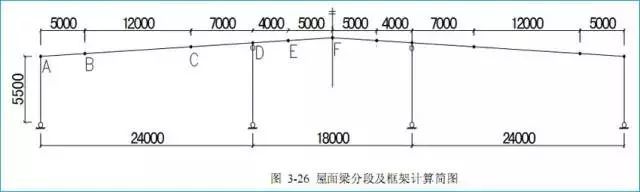
3. The setting of joints for roof beam splicing needs to consider the following factors: (1) The splicing point should be as close as possible to the reverse bending point. Generally, the position of the reverse bending point is at 1/4~1/6 span. According to this principle, for a span of 24 meters, the splicing point should be set at a distance of 24 * (1/4~1/6)=4~6 meters from the column. For an 18m span, it should be set at 18 * (1/4-1/6)=3-4. 5m, which is more suitable; (2) The unit length should not exceed the maximum transportable length, generally not exceeding 12.5 meters; (3) Minimize the number of splices as much as possible, as splicing nodes require end plates and high-strength bolts, which will also increase project costs; (4) Splicing nodes should avoid the connection positions of wind resistant columns and roof tie bars to avoid inconvenience in connection; Taking into account various factors, we have segmented the roof beams, as shown in Figure 3-26. Node A is the joint between the side columns and beams, while Node D is the joint between the middle columns and beams. Usually, the roof beams here are continuous, considering the high bending moment here. For the ridge node F, we usually do not recommend breaking the roof beams here because there are usually wind resistant columns and roof tie rods here. If roof tie rods are installed, it will cause inconvenience in connection. The 66m roof beam is divided into 7 sections. Readers can try to study other different beam segmentation methods and compare them with this plan.
4. Hinge and rigid connection settings of column base and beam column: Due to the low eaves height of this project and the absence of traffic, the column base can be treated as hinged. For the middle column, a swinging column is adopted, that is, the connection between the column and the beam adopts a hinged mode.
#building steel frame structure
Read More
For further information feel free to contact us
Email:sales@zyminfra.com
Tel/Whatapp:0086-18561962040